The importance of IEC 61850 in relation to the smart grid

By Andrea Bonetti
Many articles and papers ([1], [2], [3]) have been written and are still being written about the IEC 61850 protocols – some have even appeared in Electrical Tester ([4], [5]). This article, however, will only mention the IEC 61850 protocols briefly: its focus is on delivering the message that IEC 61850 is not “just another communication protocol”. It’s much more than that!
Smart grid and IEC 61850 in the IEC world
When we talk about the smart grid, there is always an element of doubt. What are we talking about? Do we really know what a smart grid is? To get a more formal definition of a smart grid, let’s turn to the IEC.
According to the “Electropedia”, the International Electrotechnical Vocabulary (IEV, IEC 60050 [6]), a smart grid is defined as an electric power system that uses information exchange and control technologies, distributed computing, and associated sensors and actuators, for purposes such as:
- to integrate the behaviour and actions of the network users and other stakeholders
- to efficiently deliver sustainable, economic, and secure electricity supplies
In addition, a look at the IEC website will show that IEC 61850 is one of the core standards for the smart grid [7]. Finally, the IEC Smart Grid Road Map of 2010 [8], shown in Figure 1 below, describes IEC 61850 as “substation automation and beyond,” indicating the intention, or at least the vision, to go beyond the concept of substation automation. These references make it clear that the implementation of the smart grid has a direct connection to IEC 61850. Therefore, it is relatively easy to motivate the use of IEC 61850 in projects related to the smart grid, at least in those countries where the IEC standardisation is followed. Now let’s have a look at the main concepts of the IEC 61850 standard.

Figure 1: The IEC smart grid standardisation road map, June 2010
The three pillars of the IEC 61850 standards
The three pillars of the IEC 61850 standards are:
- Standard Signal List (read as Standard Modelling and Signal Models, Information Model)
- Standard Information Exchange (read as Standard Services and Protocols)
- Standard System Engineering (read as System Engineering, Device Configuration, Documentation)
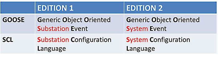
Figure 2: Examples of where the ‘S’ changed meaning from ‘Substation’ to ‘System’

Figure 3: A single line diagram in SCL/XML format
In many parts of the world, and in many applications, it would be possible to add a fourth pillar:
- Globally accepted and in use
Unfortunately, this is not universally valid, and one of the intentions of this article is to contribute to making this point the fourth pillar of the IEC 61850 standard.
Evolution of IEC 61850: from substation to power system
In 2003, Edition 1 of the IEC 61850 standard was created for substation automation. Later, around 2013 (individual parts of the standard were published on slightly different dates), the scope of the standard was expanded from substations to power utility automation so that it now encompassed interaction between substations – that is, power system activity. More informally, it is often said that the ‘S’ changed its meaning from ‘Substation’ to ‘System’, as the examples in Figure 2 show.
One of the major drivers for this change was the possibility of applying IEC 61850 in systems formed by many geographically distributed substations or, in other words, in smart grid applications.
The language is the key: SCL engineering
In IEC 61850, the language is the key. The electrical systems and their components are described through XML files. The IEC 61850 language used in the XML files is called System Configuration Language (SCL). Figure 3 shows how one substation single line diagram is described in SCL language, which ends up as one XML file.
Historically, in the application of IEC 61850 to substation modelling, ‘everything started with the brick’, and this is still the same today. The Intelligent Electronic Devices (IEDs) used in the system are described with SCL files (XML files in SCL language). These files are called IED Capability Description (ICD) files. The ICD file describes the capability of the IED hosting the protection functions (i.e. Logical Nodes, in a simple representation): how many overcurrent protections (PIOC, PTOC logical nodes) are available? Is there distance protection (PDIS)? This file is not engineered. In principal, it contains no description of GOOSE messages, no MMS reports to Station HMI or RTU, etc. Also, the IEC 61850 name (IEDName) of the device is not known, as it is "template". The JED is typically a protection device, usually a multifunctional protection relay.
In the ICD file, the relay's internal functions and signals are modelled into the standardised signals (Logical Nodes, Data Objects, Data Attributes), according to the vendor's implementation. This modeling is described in IEC 61850-4, an extract from which is shown in Figure 4.
As one substation contains many IEDs, the description of the substation is done in a special SCL file that contains a description of all of the IEDs. In simplified words, all the different ICD files from different IEDs are 'merged' together in one single file, through a special software tool called SCT (System Configuration Tool). This file is called the Substation Configuration Description (SCD) file, and it describes the IEC 61850 model of the substation in standardised SCL language. With the SCT, the 'SCL engineer' defines the signals that must be communicated between the IEDs (GOOSE) and from IEDs to Station HMI / RTU (MSM Reports), as well as the commands (open/ close, for example) from Station HMI/ RTU to the primary equipment.
The aforementioned was a simplified description of the so called 'bottom-up SCL engineering approach': You have your bricks, you describe them with the IEC 61850 models (ICD files), you tell them what to communicate through IEC 61850 SCL-described protocols, you put. all of this together and you create one SCD file, which describes your substation.
Even though this engineering process is wonderful, even more can be done with the 'top-down SCL engineering approach'.
The top-down approach starts with a specification written in an SCL file: this is the System Specification Description (SSD) file. This file provides a full description of the intended system: functionality, signals, layout (in terms of a single-line diagram) and, eventually, the communications flows. From the SSD file, devices that match the specification are created by the vendors, and they provide their ICD files that match the information model available in the SSD. At this point, it is possible to build the SCD file from the SCT tool.
This top-down engineering process is very powerful because the final user, who is responsible for the SSD file, has the control of the system from the very beginning. It is therefore possible to verify consistency between the specification (SSD file) and the system delivered by the system integrator (SCD file), assuring the required quality of the project. The top-down approach is a relatively new concept, but it is now being adopted for many projects every year.
SCL modelling and engineering are so important that the IEC 61850 standard has standardised the roles of the software tools that deal with IEC 61850 SCL engineering.
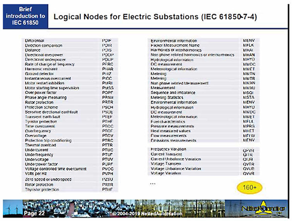
Figure 4: Logical nodes for electric substations. IEC 61850-4 (Courtesy of Karlheinz Schwarz)
The vendor tool, responsible for reading the SCD file and loading the instructions for a particular IED into the IED itself (e.g. send this GOOSE, receive this GOOSE; send this report to this RTU, etc.) is called ICT (IED Configuration Tool). The interoperability among tools is achieved through the SCL language so that tools from different vendors can exchange engineering data. As mentioned before, the tool to integrate the different IEDs into one single SCD file is called SCT (System Configuration Tool). Often this tool is a third-party tool, and it can be used for both system specification and system integration [9].
Now that we have learned (in simplified words) how to describe an electric substation, what can we do when we want to describe the smart grid? We can’t have a single SCD file describing the whole of the smart grid! Its size would make it impossible to handle. And every small change to any part of the smart grid would make it necessary to change the SCD file, which is simply not practical.
Fortunately, IEC 61850 has a procedure for describing different systems (one SCD file for each system) and the communication among them, by using a special file: the System Exchange Description (SED) file. The smart grid is made up of geographically distributed systems, so this IEC 61850 procedure potentially provides SCL engineering methods that can be used for smart grid applications, as shown in Figure 5.
To apply this engineering and description concept to the smart grid, however, we need standardised models with their SCL descriptions to cover the full range of smart grid applications. Do we have them?
Standardised IEC 61850 models beyond substation automation
In fact, many models already exist, and many more are under development. There is definitely a lot of enthusiasm in the electrotechnical community for IEC 61850 modelling!
IEC 61400-25 and IEC 61850-7-420, for example, provide standardised models for wind turbines and photovoltaic systems; technical report IEC 61850- 90-7:2013 contains standardised models for power converters in distributed energy resource (DER) systems; and IEC 61850-7-410:2010 has details of standardised models for hydro power plants.

Figure 5: Method for describing a distributed system in SCL, by describing each subsystem and the data exchange among them
All of these models have been available for many years, but there has only recently been a dedicated focus on using them. This is probably because of the availability of third-party SCL engineering tools that facilitate the use of multivendor systems, along with navigation through the standardised models with comprehensive libraries.
An important example relates to the Italian company, Enel Green Power, that recently (2019) decided to adopt IEC 61850 for the automation of power plants with various generation technologies (hydro, wind, solar, geothermal and cogeneration). In the presentations shown at the Hydro Symposium in Italy (January 2020), the focus was on the modelling of their systems (Figure 6).
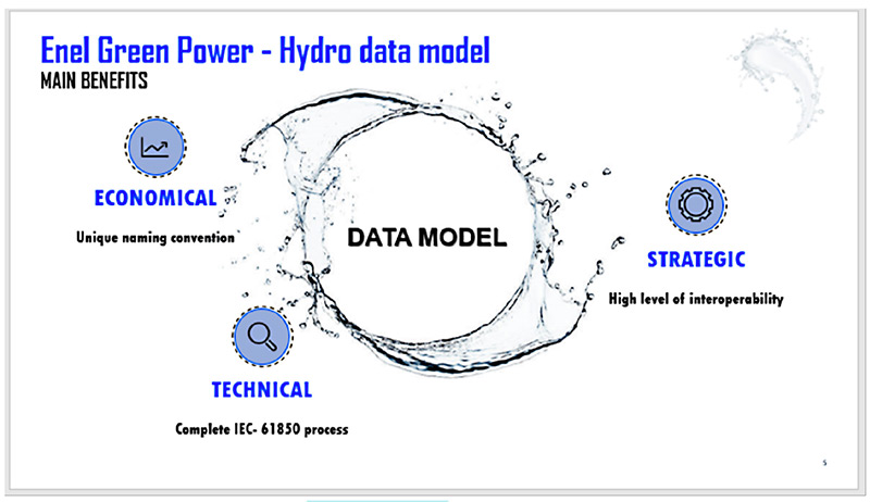
Figure 6: Extract from presentations at Enel Green Power Hydro Symposium. The data model is the focus (2020)
IEC 61850 protocols
Only now that we have reached this point is it possible to talk about protocols and communication media. There is already much literature on this subject, so only the basic concepts are described in this article.
The IEC 61850 protocols are standardised to ensure interoperability among devices from different vendors. Each device has the so-called IEC 61850 stack implemented and is able to understand the information delivered with the different protocols. Not all protocols may be implemented; this depends on the application for which the device is designed.
The IEC 61850 stack in the device is 'programmed' using the information available in the relevant SCL file. The file is read by the ICT (IED Configuration Tool) and the communication stack is programmed by the ICT, following the described IEC 61850 engineering process.
To communicate data 'within the substation', the following protocols are currently available and in use:
- GOOSE (Generic Object Oriented System Event) - Publisher/Subscriber. This is the real time standardised protocol for protection and interlocking schemes (horizontal communication).
- SV or SMV (Sampled Values) - Publisher/Subscriber. This is the real-time standardised protocol for communicating sampled analogue quantities via digital media.
- MMS (Manufacturing Message Specification) -Client/Server. This is the standardised protocol for communication of events, commands, disturbance files to SCADA/RTUs (vertical communication).
To communicate data 'between substations', IEC 61850 provides the following protocols, which are considered to be new:
- R-GOOSE (Routable GOOSE)
- R-SV (Routable Sampled Values)
- MMS
- XMPP -Web Services, IEC 61850-8-2:2018 (which provides the specifications for mapping IEC 61850 MMS and time synchronisation messages to XMPP)
Where does the real power of IEC 61850 lie?
The real power is that IEC 61850 modelling is not affected by the communication protocol. What is specified/described in SCL is what standardised IEC 61850 information goes from where to where. Depending on the application, SCL describes some protocols (GOOSE, MMS, Sampled Values) that are standardised.
We might, for example, tell the IEC 61850 tool that we want to “send this information via GOOSE”. The IEC 61850 tool describes this in SCL and provides the SCD file. The SCD file is read by the device (via its ICT tool) and it will deliver the appropriate information via a GOOSE message, as requested.
What happens if, tomorrow, there is a new protocol, much better than GOOSE, which, for the purposes of this article we will call DUCK? Let’s hypothesise that this new DUCK protocol is much better, faster, easier, and cheaper because it was developed in 2021, and now we all want to use DUCK for communication.
At this point, the community needs to agree that DUCK is an IEC 61850 protocol and standardise it. DUCK will be described in SCL and it must be implemented in the devices (IEC 61850 stacks). Once this is done, it is possible to ask the IEC 61850 tool to “send this information via DUCK”. The tool describes this in SCL and provides the SCD file. The SCD file is read by the device and it will deliver the appropriate information via a DUCK message, as requested.
Without having changed anything in the data model of the system and in its functionality, the messaging is now using the new DUCK protocol. Please note for emphasis that DUCK doesn’t exist! It is just a hypothetical situation used to illustrate how IEC 61850 is future-proof, ready for every technical improvement, including improvements to communication protocols.
Conclusions
It is fair to say that IEC 61850 provides all of the tools needed to manage the design of the smart grid.
The main advantages of the data modelling/SCL description and engineering of IEC 61850 systems can be summarised as:
- Common language and shared understanding: Thanks to standardisation, third-party companies are open to investing in the production of SCL tools
- Minimises misunderstandings at the specification phase: Possible to validate the delivered system by checking its consistency with the formal description in the specification
- Clear ‘as built’ description (documentation) for the installed system: Possible to perform automatic maintenance routines for the smart grid system by automatically comparing the status of the communication system with its description on the master SCL file [10], [11]
Going back to the smart grid definition in the IEC Electropedia, three points are very important:
Information exchange: It is clear that there is no consistent information exchange without the use IEC 61850.
Secure electricity supply: Continuous self-supervision, self-maintenance and many other procedures will make the power system more secure, as it will be able to give automatic information about faults, as soon as they are detected, improving the MTTR of the system.
Economic electricity supply: We need to study and get used to IEC 61850 methods, but once this is done, the economic advantage is evident: reusability of previous projects, shared understanding, focus of the technical community on solving common problems, and concentration of the resources.
In conclusion, I hope it is now clear that IEC 61850 is not just a communication protocol but a complete philosophy for electrical systems. So, next time you have a smart grid project, please try to answer this question: How much of IEC 61850 am I using in my project?
Acknowledgements
This article is based on a keynote address presented by the author at the IEEE GPECOM online conference in October 2020. The author would like to thank Karlheinz Schwarz for his active contribution and support for the keynote. Thanks also go to Marco Pinelli and Roberto Guida, Enel Green Power SpA, and Giuseppe Rigadello, Enyr Srl, for allowing me to publish some figures and information about the recent Enel Data Model project on IEC 61850 modelling for hydro power generation.
About the author
Andrea Bonetti
Andrea is senior specialist in relay protection and IEC 61850 applications at Megger Sweden AB, Stockholm, Sweden.
Full details of Andrea’s profile are available on LinkedIn: https://www.linkedin.com/in/bonetti-andrea/
===========
References
[1] A. Bonetti and R. Douib, ‘Transfer time measurement for protection relay applications with the IEC 61850 standard’, in 2010 IEEE International Symposium on Electrical Insulation, Jun. 2010, pp. 1–5, doi: 10.1109/ELINSL.2010.5549563
[2] A. Bonetti, ‘IEC 61850 GOOSE Interoperability’. Megger Sweden AB, Jan. 2010, Accessed: Jun. 16, 2020. [Online]. Available: https://www. researchgate.net/publication/330762058_IEC_61850_GOOSE_Interoperability
[3] M. Sharma, L. Nguyen, S. Kuber, and D. Baradi, ‘Testing IEC-61850 Sampled Values-Based Transformer Differential Protection Scheme’, presented at the Pac World Americas, Oct. 2019, Accessed: Jul. 23, 2020. [Online]. Available: https://www.researchgate.net/publication/336878700_Testing_IEC-61850_Sa…
[4] A. Bonetti and M. Pitzer, ‘Electrical Tester: Q&A about IEC 61850’, Feb. 17, 2020. https://megger.com/electrical-tester/february-2020/q-and-a-iec61850 (accessed Nov. 03, 2020)
[5] M. Dhanabal, ‘Electrical Tester - Experiences with IEC 61850 in commissioning a high voltage reactor’, Jan. 04, 2015. https://megger.com/electri-cal-tester/april-2015/experiences-with-iec-6… (accessed Nov. 03, 2020)
[6] ‘IEC 60050 - International Electrotechnical Vocabulary - Details for IEV number 617-04-13: “smart grid”’. http://www.electropedia.org/iev/iev. nsf/display?openform&ievref=617-04-13 (accessed Sep. 18, 2020)
[7] ‘IEC 61850: core standards for the smart grid | IEC’. https://www.iec.ch/blog/iec-61850-core-standards-smart-grid (accessed Apr. 20, 2021)
[8] ‘IEC Smart Grid Roadmap’. https://www.iec.ch/smartgrid/downloads/sg3_roadmap.pdf (accessed Oct. 09, 2020)
[9] C. Brunner, D. Muller, M. Demierre, J. Reuter, E. Cottens, and D. Badoux, ‘Focus on the application – IEC 61850 experience with third party system configuration tool’, p. 10
[10] A. Bonetti, N. Ignatovski, and S. Fernandez, ‘Providing an IEC 61850 Counterpart of the Trusty Multimeter - Approaching the Maintenance Procedures for IEC 61850 Substations’, in 2019 1st Global Power, Energy and Communication Conference (GPECOM), Jun. 2019, pp. 440–444, doi: 10.1109/GPECOM.2019.8778541
[11] A. Bonetti, S. Fernandez, M. Urosevic, R. Yalda, and N. Ignatovski, ‘Event driven maintenance for IEC 61850 Substations Periodic comparison of GOOSE data flow and of automatic post-fault analysis results’, presented at the MATPOST 2019, Lyon, FR, Nov. 2019, Accessed: Jun. 16, 2020.
[Online]. Available: https://www.researchgate.net/publication/337496394_Event_driven_mainten…


