VLF testing on motors and generators
By Hein Putter
The unexpected shutdown of an HV rotating machine is, in almost every instance, hugely disruptive and very costly. Research has shown that the most common reason for such shutdowns is a fault in the stator winding insulation – such faults account for 60 % of failures in large HV synchronised motors. Similar results have also been found in hydroelectric generators. Therefore, it is important that the stator winding insulation be exhaustively tested both in the factory, before a machine is dispatched, and as part of the acceptance testing, after the machine has been installed on site.
Hi-pot testing
The most widely used form of testing is the highpotential – or more informally, ‘hi-pot’ – test, which is used in the factory and on site (typically as a field acceptance test but also gaining accolades in its use thereafter) to verify the ground wall insulation of the stator winding. The hi-pot test is a withstand or overvoltage test that essentially involves applying a voltage to the machine that is above its nominal operating voltage, while looking for signs of an insulation breakdown. The test detects local weak spots in the insulation, thereby giving a preview of its condition before deterioration leads to the point that a line voltage test results in a ‘fail’ assessment that you are not prepared to remedy immediately or, worse, an in-service failure. Hi-pot tests cause existing insulation weak spots to fail and are therefore performed during a scheduled outage, in controlled test conditions, with contingencies if the machine fails. However, provided they are carried out correctly, hi-pot tests do not create new weak spots. It is important to note that hi-pot tests are ‘go/no-go’ tests; if detailed diagnostic information is needed, they must be combined with, for example, partial discharge and tan delta/power factor tests.
Hi-pot tests can be performed with three test voltage types: DC, AC at power frequency, and AC at very low frequency (VLF). The frequency used for VLF testing is usually 0.1 Hz. The reason for the emergence of VLF testing is that the test equipment needed is significantly smaller and less costly than that needed for power frequency testing, while the voltage distribution it creates in composite dielectrics can still closely resemble that produced at power frequency.
Hi-pot and cables
In a move that began in the 1980s, VLF hi-pot testing has largely supplanted DC testing for cables. This change was primarily driven by experiences with MV cables which, prior to the 1980s, were usually paper insulated lead covered (PILC) types. When polymer insulated types (XLPE, EPR) were introduced, it was found that there were numerous post-test failures after DC tests had been performed on aged cables. Ultimately it was discovered that local trapped space charges at insulation defects, such as water trees, developed in XLPE and EPR cables when subjected to DC voltage.
More specifically, DC testing, which was sometimes carried out with test voltages up to eight times the cable’s nominal voltage rating, caused residual space charges to be generated in aged cable circuits. These behave like RC circuit elements with very long time constants of many hours or even days. Even if the cable is correctly discharged, these space charges dissipate very slowly. Suppose the cable is returned to service before dissipation is complete. In this case, the interaction between the space charge and the electric field produced by the cable’s normal operating voltage leads to very high local field stress at the space charge locations, often resulting in insulation breakdown. It has also been found that DC testing is unable to detect certain types of defect, such as voids, cuts and wet faults, irrespective of cable type, and that these shortcomings persist even though DC testing is performed at a higher voltage than VLF tests.
Hi-pot and motors
Motor testing is now following the cable test trend away from DC to VLF for hi-pot testing. However, VLF testing of motor stator windings is not a new idea, having been proposed by Bhimani in the 1960s. The IEEE433-1974 standard was first to reference VLF testing of rotating machines, and it was updated in 2009. Price was initially a barrier to the adoption of VLF testing for motors, but prices of VLF test sets have fallen markedly over the last decade, so this is no longer a critical issue, especially as VLF offers so many benefits.
Not the least of these benefits is that voltage distribution in stator insulation at VLF corresponds significantly better with the motor’s normal operating conditions than it does in DC testing. Another important advantage is that due to the lower reactive power requirement for tests at VLF compared with tests at operating frequency, VLF sources are smaller, lighter and therefore more mobile. This is particularly useful in applications where the test equipment’s weight and size may otherwise render testing impractical, such as when working on wind turbines. Further, as VLF test sets typically support higher loads, it is often possible to test stator windings, including the MV cable, directly from the MV switchgear. This is not permissible with DC testing and is usually not possible with power frequency testing.
Two standardised technologies are now widely used for VLF testing: VLF sinusoidal and VLF cosine-rectangular. VLF sinusoidal testing, as the name suggests, uses a sinusoidal waveform. In contrast, VLF cosine-rectangular testing uses a waveform akin to a square wave with a defined rise and fall time that closely matches the rise and fall time of a power-frequency sine wave. The most important characteristics of these two technologies are summarised in Table 1.
Test voltages
Extensive research has been carried out to determine the optimum test voltage for VLF testing at 0.1 Hz compared with testing at power frequency. For power frequency testing on new stator windings, the formula normally used is:
U test_60 Hz_RMS = 2 U o + 1000 1V
This means, for example, that a 6.9 kV motor will be tested at 14.8 kV RMS, and a 13.8 kV motor at 28.6 kV RMS. For VLF testing, empirical data for asphalt-mica insulation systems shows that these voltages should be multiplied by a factor of 1.63 to give the peak test voltage, so that the formula becomes:
U test_VLF_Peak = (2 U o + 1000 V) x 1.63
In other words, at VLF, the 6.9 kV motor is tested at 24.1 kV peak and the 13.8 kV motor at 46.6 kV peak.

Note that the foregoing figures apply to new machines. For maintenance proof testing, in general, a powerfrequency test voltage ranging between 125 % and 150 % of rated (RMS) terminal voltage has proved adequate (IEEE Std 56), and the same multiplier of 1.63 is applied to determine the VLF test voltage (peak) - see the examples in Table 2.
VLF testing of motors
VLF testing on machines can be performed without the rotor in place or, provided that suitable precautions are observed, with the rotor in place. Appropriate electrical clearance for terminals is needed. IEEE 433 describes additional precautions to be taken depending on whether the machine is air-, hydrogen-, liquid- or oil-cooled. Wherever possible, VLF testing (as with power frequency testing) is performed on each phase separately, with the other phases grounded. Suppose it is not possible to test the phases individually and all phases have to be tested together. In that case, the test result will relate only to the insulation to ground - the phase-to-phase insulation will not be tested. The recommended procedure for VLF testing is to select the correct test voltage on the test set, then apply it for a minimum of 10 full cycles of the test voltage, which, at 0.1 Hz, corresponds to 100 seconds. No breakdown shall occur during the test. After the test, all phases and windings of the machine must be earthed for at least 15 minutes.
VLF for diagnostic testing
As has already been mentioned, a hi-pot test, irrespective of whether it is performed using a DC, VLF, or AC power frequency test voltage, is a pass/fail test that provides no diagnostic information about the condition of the stator insulation. For this reason, additional diagnostic tests are recommended for rotating machines, just as they are for cables. Typical diagnostic tests performed on stator windings are:
- Insulation resistance (IR) testing
- Polarisation index (Pl) testing
- Power factor/dielectric loss/dissipation factor/tan delta (TD) measurement
- Partial discharge (PD) measurement
- There are IEEE standards (IEEE 286 and IEEE 1434) for dissipation factor measurements (TD) and PD measurements at power frequency
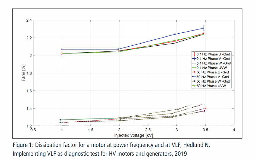
Most commercially available VLF test sets can be used for TD measurements and for PD diagnostics. Apart from TD step tests, one can also monitor the losses during the withstand tests to gain more information about the stator winding condition. With DC tests, the equivalent parameter during the hi-pot test is the leakage current, while with VLF sinusoidal, the losses are monitored. As yet, no threshold values are available for VLF 0.1 Hz TD testing, but it is known that loss values are higher and, as with cables, ageing can be recognised more easily at low frequencies than at power frequency (see Figure 1).
The classical way of representing the dissipation factor of stator windings is to use the tip-up value, which is calculated by subtracting the TD value measured at 20 % of the machine’s nominal operating voltage from the TD value measured at the full nominal operating voltage. That is:
Tip-up = TD @ Uo – TD @ 20 % of Uo
When losses are displayed as a function of voltage, it is possible to see where PD starts, as the losses will increase at this point. In fact, the tip-up test basically gives an indirect indication of the amount of PD but, for those defects where the PD repetition rate is low – with loose coils in a slot, for example – the influence is small. It is also important to note that if there is a silicon carbide stress control coating on the coils, this will affect the tip-up value. Also, both the dielectric losses and the tip-up value will be influenced by the type of insulation used. Trending values over time will, therefore, give the best information about the condition of the stator winding.
Recent findings on VLF TD measurements
The Electrical Power Research Institute (EPRI) has recently reported some important and interesting findings relating to VLF TD measurements on motors (G Toman, 2017). The major findings are:
- VLF TD measurements can be used to differentiate between good motors and motors with deteriorated insulation walls
- Three VLF assessment techniques – absolute value, tip-up value and % standard deviation – are useful for assessing motors
- Combined motor/cable circuits can be assessed using VLF TD measurements
- VLF testing of motors with non-shielded cables attached provided surprisingly good results
- Good motors have low absolute TD and moderate tip-up; deteriorated motors have high absolute TD and/or high tip-up
The VLF TD values on good motors tested by EPRI ranged from 5 % to 15 %. Decreasing TD values with increasing voltage were reported as a concern, as they may indicate moisture leaving a tracking site. Increasing TD values are also problematic as they indicate an excessive effect of increasing voltage, suggesting that some form of insulation breakdown may be occurring as the voltage increases. Increasing TD values may occur while applying a stable voltage, in which case an electrical tree is growing, and a breakdown may happen soon. The larger the electrical tree, the higher the number of discharges and the higher the losses will be.
Overall conclusions from the EPRI report are that VLF TD testing is indeed a useful technique for evaluating motors and motor/cable circuits. All three assessment methods
(absolute value, tip-up value and % standard deviation) should be used, and trending results over time further improve the technique’s value. The report also notes that combined circuit (motor/cable) acceptance criteria are different from cable acceptance criteria when considering absolute tan delta and tip-up values, but the % standard deviation may be the same, or almost the same, as for cable. The % standard deviation will be slightly higher for motors alone than for cables alone.
In summary, VLF testing is a very good alternative for hi-pot testing and dielectric loss measurements on stator windings. Not only are the weight and dimensions of these test units a huge benefit, but also the power output, compared to power-frequency test sets, is considerably higher. Further, the dielectric loss measurements, which are integrated with most VLF test sets, enable an easy and proper way to assess a machine’s condition. Based on the test results, one can schedule corrective maintenance actions and prevent unexpected outages.
Megger offer a large range of VLF test sets with diagnostic capabilities to help you assess the condition of your motors and generators. What’s more, Megger also provide turn-key solutions for online monitoring of machines as well as testing equipment such as rotating machine testers, static testers, and dynamic testers. One supplier for all your needs!


