DELTA4000 series 12 kV power factor/tan delta testers
Confidence in AC insulation with narrowband DFR (1 to 500 Hz)
Identify developing problems in insulation that are hidden at line frequency (50/60 Hz)
Designed for all environments
Two-piece design, weighing 14 kg and 22 kg, saves on effort, space, and shipping costs
Accurate measurement results under high noise conditions
Noise suppression and advanced signal acquisition circuitry handles up to 15 mA interference current or a 1:20 signal-to-noise ratio
Patented built-in Individual Temperature Correction (ITC)
Eliminates the need for generic temperature correction tables and allows the user to calculate the actual temperature dependence
About the product
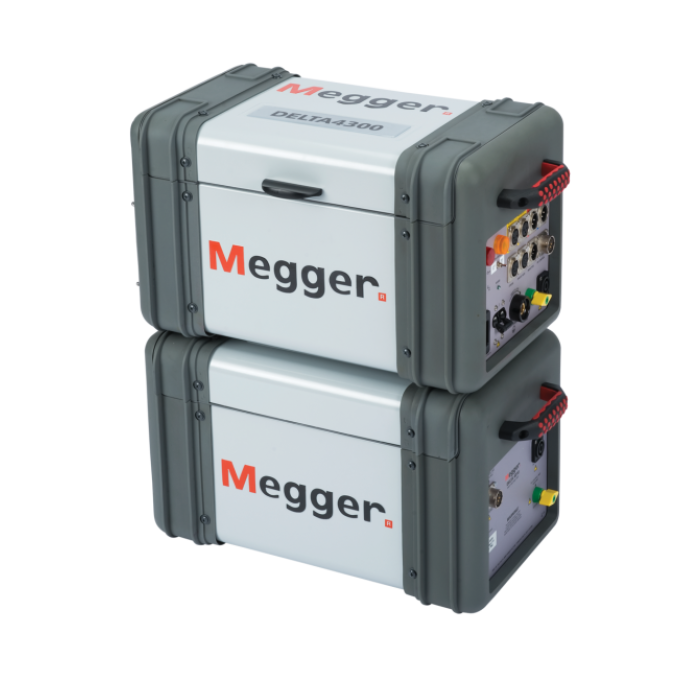
The DELTA4000 is an automatic 12 kV insulation power factor/tan delta test set designed for the immediate condition assessment of electrical insulation. In addition to traditional power frequency (50/60 Hz) testing, the DELTA4000 uses 1 Hz power factor/tan delta to enhance power frequency assessment of high voltage transformers, bushings, circuit breakers, cables, lightning arresters, and rotating machines. Using the same connection and software as power frequency tests, 1 Hz improves maintenance planning by reducing the need for historical trending and proprietary databases.
The high power variable frequency design generates its own test signal independent of line frequency quality, and the hardware design uses the latest technology available for digital filtering of the response signal. As a result, the DELTA4000 series produces reliable results and stable readings in the shortest time with the highest accuracy, even in high interference substations.
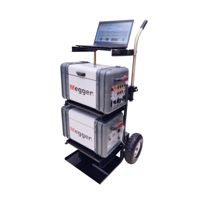
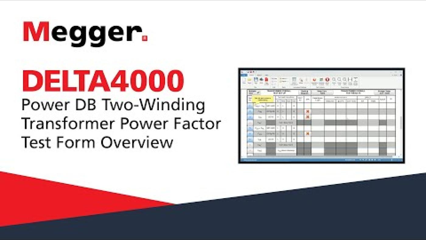
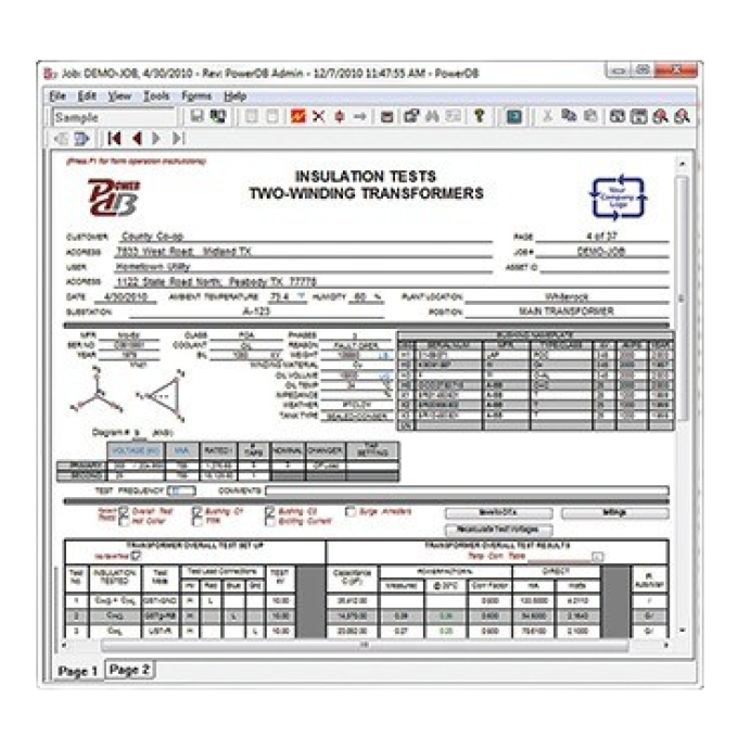
The DELTA4000 series operates with PowerDB software for automatic testing and reporting or with Delta Control software for real-time manual testing.
Measurements include voltage, current, power (loss), power factor/tan delta, inductance, power factor, and capacitance. The test results are automatically stored in the computer and can also be downloaded directly to a USB drive or a printer.
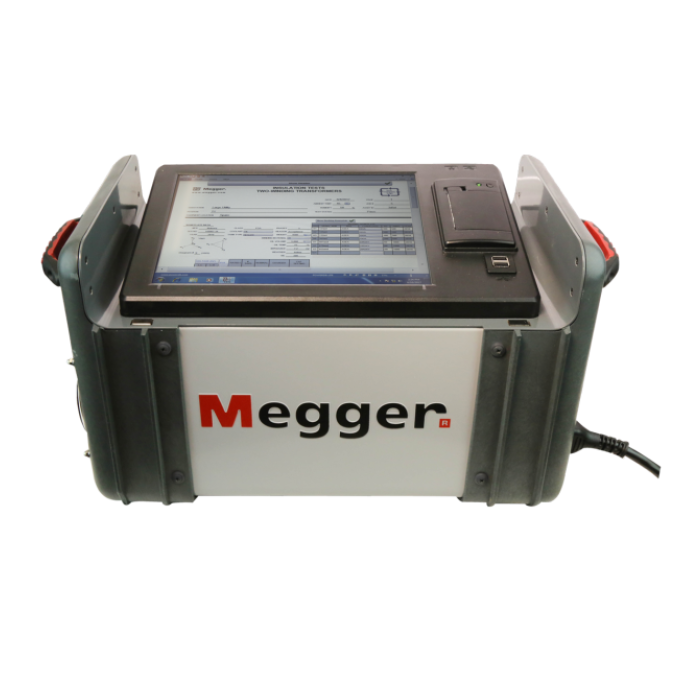
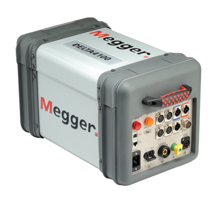
The DELTA4110 test set is to be used with an external computer (not included), while the DELTA4310A test set comes with its own on-board computer.
Technical specifications
- Input voltage
- 90 - 264 V, 45 - 66 Hz
- Max output current (AC)
- 300 mA (4 minutes)
- Max output voltage (AC)
- 12 kV
- Test type
- Capacitance and dissipation/power factor
Further reading and webinars
Troubleshooting
First check that the specimen under test and the DELTA are properly grounded. If the problem persists, the culprit could be the high voltage cable. Rough handling in substation environments generally causes physical damage rather than electrical. To check its integrity, hang the cable free in open air and energise it to no more than 5 kV. In low humidity, a good cable will typically emit no more than 4 to 8 picofarads (pF), with low dissipation factor (or tan delta). If the capacitance exceeds these levels and/or the power factor/tan delta is greater than 2 %, the cable will need to be returned to Megger for re-termination.
Verify that there are no unwanted grounds connected to the specimen under test. Perform an open air test as detailed above and verify readings again. If the readings are still too high, it may be that the guard contact spring on the HV DELTA unit has become thin. In this condition, the spring is easily damaged when the cable is pushed on roughly. This affects the GST measurement reading and can also be affected by a guard-to-ground short. You will need to return your DELTA unit to Megger for repair.
If the inverter trips, the DELTA is drawing too much current. An inverter trip can often signify that a ground or measurement lead is connected to a common point where you are applying test voltage. Verify that there are no unwanted grounds connected to the specimen under test. Also, check that you have not left any shorts connected between the points where you are applying voltage and measuring. Unwanted grounds can be safety grounds left on the transformer; they can also be station grounds connected to the neutral of a WYE winding. Note: WYE windings may have an internal ground you may not see; check the nameplate to verify that the winding is not grounded internally. Some WYE WYE transformers have their internal neutrals shorted together. If you cannot disconnect this internal short, you will only be able to perform a GST type test.
If you are performing excitation testing, the inverter may trip before reaching 10 kV on one winding but not the others. This behaviour may be due to the design of the transformer and the current required to excite the windings. If this is the case, we recommend testing all three windings at the same voltage level (close to but less than the tripping voltage) to have comparable results.
If there are no unwanted grounds or shorts and the inverter is still tripping while performing an insulation test, perform an open air test as discussed above. If the inverter is still tripping, you must send the DELTA to Megger or an authorised repair centre.
Restart the unit and try communication again. If using an external PC, unplug the communication cable and plug it back in before powering on the DELTA. A switch on the control unit allows you to select either internal control with a built-in computer (INT PC) or external control with your PC (EXT PC). Verify that this switch is in the correct position for the computer you are using. If you change the switch, you will need to power off the DELTA and then power it back on. There are two communication methods between a PC and the DELTA; some companies' security settings may limit one or the other. If connecting via USB is not working, try connecting with an Ethernet cable or vice versa.
For safety, you must connect the test ground of the DELTA to the same ground of the mains power supply that is powering the DELTA. There is an internal circuit that verifies this. Check to make sure your extension cord and power outlet have a working ground connection. If powering the DELTA using a generator, you must correctly ground the generator to the station ground. Verify that your test ground is solidly connected; occasionally, paint or corrosion may be at the connection point and will need to be cleaned before connecting the test ground for a solid electrical connection.
Ideal insulation has a power factor (PF)/tan delta value of zero. However, this is not possible in the real world, so even though the PF/tan delta can be small, it should always be greater than zero. External factors can cause alternative leakage paths that affect PF results. If you have a negative PF, know that this is a phantom value, and you will need to check connections. First, check your ground (or earth) connections, verify that you have a solid connection between the test ground and the asset ground, and clean the connection point if needed. Negative PF values can also be attributed to environmental factors such as high humidity and excessive dirt that result in external leakage current. Cleaning/drying external bushing surfaces with a clean, dry rag can help minimise these effects. Effective use of the guard circuits can also help eliminate external leakage current. Negative values can also be attributed to specific designs, e.g., an electrostatic grounded shield between the windings of a transformer.
This error indicates a communication failure between the DELTA control unit and the high voltage (HV) unit, typically due to a faulty control cable. If the control cable is not correctly positioned when you plug it in, subsequent twist/lock manipulations of the cable damage its coaxial pins. This action can also damage the receptacle on the unit. If you are experiencing this issue, you will need to replace the control cable.
Interpreting test results
Assess capacitance (which correlates with the measured ‘total charging current’) before you assess power factor! Capacitance, among other benefits, provides confirmation that you are measuring what you are intending. When compared to a previously measured capacitance result, there should be no appreciable change. A previous capacitance measurement could be one made by the OEM (original equipment manufacturers) or one made during the tested asset’s service life. If capacitance is drastically different, check your test connections, make sure the asset under test is physically and electrically isolated and grounded well, and repeat the test. If capacitance seems reasonable, evaluate its change, if any, from previous tests.
Example: For a transformer, a change in capacitance over 1 – 2 % is worrisome. For a bushing, a change in capacitance over 5 % is concerning and one over 10 % warrants the bushing’s replacement.
In most cases, a lower power factor (PF)/tan delta test result indicates an insulation system in better condition than one with a higher PF/tan delta. PF/tan delta is assessed based on its ‘temperature corrected value’. PF/tan delta increases in the presence of contamination and as insulation deteriorates, and is sensitive to temperature. To rule out temperature, therefore, as the cause for an increase in PF/tan delta from a previous or benchmark value, it is important to analyse PF/tan delta test results that reflect a 20 °C equivalent result. These are referred to as ‘temperature-corrected PF/tan delta’ test results. Megger’s DELTA test instrument determines these values automatically, applying a correction algorithm that uses as its inputs, measured values that reflect the actual condition of the asset under test.
Compare the ‘corrected PF/tan delta’ to a previous measured value or to a standards table of PF/tan delta test results typical for the asset under test. Any increase should be viewed sceptically. This is a good test to identify electrical insulation health that is in decisively bad condition. This is not a good test to determine conclusively if insulation health is good, or to gauge the status of insulation health that is neither good nor bad. For more discerning insight, perform a 1 Hz PF/tan delta with the Megger DELTA instrument.
Power factor (PF)/tan delta tests performed using a 1 Hz voltage source are far more sensitive to the presence of contaminants, such as moisture, than PF/tan delta tests performed using a line frequency voltage source.
As with a line frequency PF/tan delta test, results from a PF/tan delta test performed at 1 Hz should be compared with previous test results, if available. Short of that, Megger has developed the following guidelines for assessing temperature corrected, 1 Hz PF/tan delta test results.
OIP Bushing Insulation Condition | 1 Hz DF at 20 ℃ |
---|---|
As new | 0.2 - 0.5 |
Good | 0.5 - 0.75 |
Aged | 0.75 - 1.25 |
Investigate | >1.25 |
OIP Transformer Insulation Condition | 1 Hz DF at 20 ℃ |
---|---|
As new | 0.2 - 0.75 |
Good | 0.75 - 1.25 |
Aged | 1.25 - 2.0 |
Investigate | >2.0 |
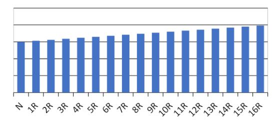
Analysis of excitation current (Iex) and loss test results for three phase transformers is chiefly based on pattern recognition. Analysis of ‘Iex and loss’ test results for single phase transformers is predominantly done by comparing these measurements to previous results.
A phase pattern is the pattern exhibited by the exciting current (or loss) test results measured for a transformer’s three phases. An H-L-H phase pattern is expected for most transformers. For example:
21.6 mA – 10.7 mA – 21.3 mA and 145.3 W – 71.4 W – 146.9 W
Conversely, a L-H-L pattern may be obtained for a four-legged core-form transformer or for a typical three-legged core-form transformer when precise test hookups are not followed in preparation for this test. A phase pattern of three similar readings is characteristic for a five-legged core or shell-form transformers with non-delta secondary windings. A problem generally manifests as three dissimilar readings. However, in these cases, it is necessary to rule out excessive core magnetisation as a root cause. Three dissimilar readings may also be obtained if the excitation current, which is typically a capacitive current, is instead dominated by its inductive component. In these cases, if the loss test results exhibit an expected phase pattern, the atypical excitation test results should be accepted as normal for the transformer.
When tests are performed on a load tap-changing transformer, the ‘LTC pattern’ is assessed as well. This is the pattern exhibited by the excitation current (or loss) test results measured within a single phase as the on-load tap changer (OLTC) is moved through each of its tap positions. There are 12 possible LTC patterns that depend on the design of the OLTC. 11 of these patterns represent normal variations that may be seen in test results for reactive type OLTCs, which are in predominant use in North America. For resistive type OLTCs, which are in widest use worldwide, an expected OLTC pattern is provided below.
User guides and documents
Software and firmware updates
DELTA41XX and DELTA43XX
Delta Control Installer
latest version
The Megger Valley Forge, USA factory and select Megger Authorized Service Centers (ASCs) can perform updates. If you do not feel capable of performing updates properly, please contact your nearest Megger sales representative for information on where to return your instrument for updates.
Carefully read all instructions and backup your data before performing any updates.
Only update the firmware or software if you are experiencing difficulty with your instrument or if you have a specific need to do so.
!! WARNING !!
Incorrect installation of updates and incomplete updates may cause an error and make the equipment unusable.
If damage occurs from improper updates, customer is responsible for repair costs.
Transformer Test Instrument Software Updates for MWA330A and DELTA4310A
Update Instructions
Please read these instructions before performing the update, you can download them here.
DELTA and MWA Updater
latest version
The following components have been updated:
PowerDB ________________ V11.2.10
MTOTestXP ______________ 2019.12.03.1
Delta Manual Control ______________ 2.0.9.51.0
Instrument Config ______ 1.0.20023.1919
Splash Screen __________ 1.0.21075.830
Factory Config _________ 1.0.21122.850
Megger Update Manager __ 1.0.21165.1032
Recommendations
- Megger recommends that you return your instrument annually for calibration verification.
- Any instrument returned for re-calibration will be updated with the latest firmware and software versions.
- Certified Factory Calibration is valid for one year.
Attention
Incorrect installation of updates or incomplete updates may cause the equipment to become unusable.
If damage occurs from improper updates, the customer may be responsible for repair costs.
Software updates for MWA330A and DELTA4310A
Download this zip file, extract, and run the executable.
256bit Hash:
be0628b2014fffeca839036dae42c3d1a6c5c73d79a2e5f2fc6d0716667ef9d3