New
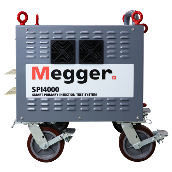
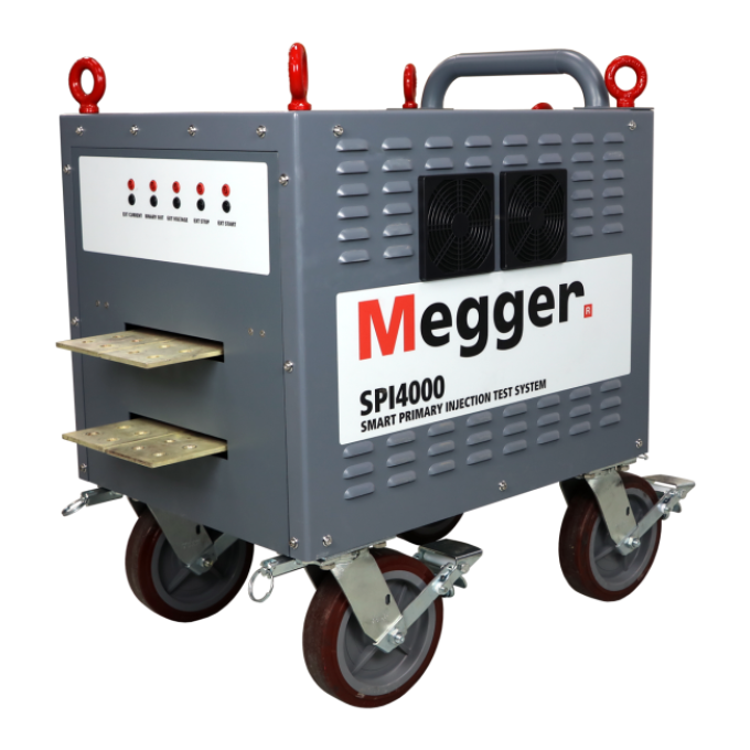
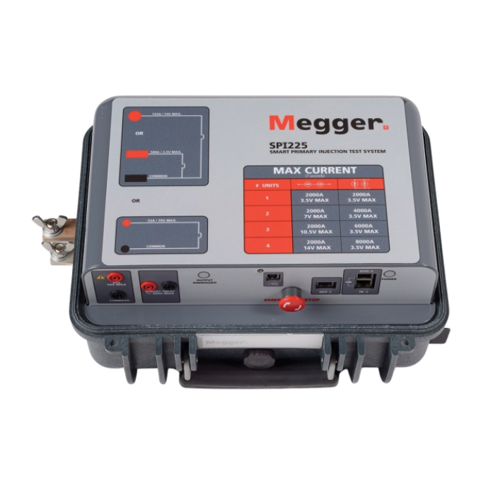
SPI4000 smart primary injection test system
Space-efficient power for testing even in the tightest quarters
The SPI4000, the smallest primary injection test system in its class, packs a punch with its compact design. It not only fits seamlessly into tight testing environments but can also slip through standard door openings, ensuring testing power wherever you need it.
High current capacity
With a maximum frame size of 4000 Amps, the SPI4000 excels in providing substantial current levels for precise testing of circuit breakers and related equipment, ensuring it meets the demands of industrial and electrical applications.
Exceptional mobility, guaranteeing your testing equipment is ready and onsite when you require it
Weighing only 514 lbs, the SPI4000 is remarkably lightweight for a high current primary injection test system. Its portability not only simplifies transportation but also reduces shipping costs, making it an economical choice for users requiring mobility and ease of relocation
Effortless precision with automatic zero crossing
One of the unique features of the SPI4000 is the ability to automatically adjust the output firing angle at the current zero crossing for every load. This eliminates DC offset for all circuit breaker types and removes the need for manual adjustment of firing angles, streamlining the testing process and ensuring accuracy across different loads and circuit breakers.
About the product
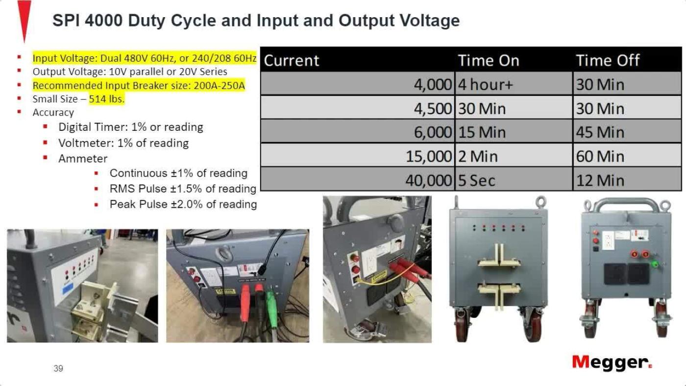
The SPI4000 is a high current primary injection test system with the flexibility to test, via primary injection, a wide variety of devices, including low voltage power circuit breakers, moulded-case circuit breakers equipped with thermal magnetic or electronic trip devices, overcurrent relays, and thermal relays. Designed to accommodate circuit breakers with ratings of up to 4000 Amps frame size, the SPI4000 fully complies with NEMA AB-4 test guidelines.
The SPI system is the first high current test system that allows you to type in a predetermined current amplitude and will then generate and regulate the requested high current without preheating the test sample by pulsing the output current at high amplitudes. Additionally, the SPI system has the unique ability to turn on at the current zero crossing every time for any load by automatically adjusting the output firing angle. This eliminates DC offset for all circuit breaker types and eliminates the need for you to determine and manually adjust the firing angle for various loads and circuit breakers.
FAQ / Frequently Asked Questions
The SPI4000 can be lifted with a forklift using the under carriage of the unit. Additionally, straps or chains could be attached to the unit’s lifting eyes. For ease of loading in vans or trailers, there are two eye hooks on the side that allow the SPI4000 to be hoisted up a ramp.
We offer two models. One model features wheels similar to the DDA units, which are solid wheels. These wheels are great for concrete floors and will not go flat. The second model is equipped with pneumatic wheels, which are recommended for navigating rough terrain.
The SPI4000 comes with an adaptor plate that allows existing DDA stabs to work with the unit. It also has a connection point for flexible stabs.
The SPI4000 is autosensing and will detect and operate on 240 V. You don’t need to change taps or anything else as the unit will autosense input voltage.
We recommend that you use a 150 kVA or larger generator with the SPI4000. Nevertheless, the SPI4000 can generate sufficient current to test most breakers, even with a generator as small as 75 kVA.
The SPI4000 was tested on generators of various sizes and exhibited no operating issues. When operating on generator power, the limiting factor for output current will be the generator’s output voltage. During high current tests, the generator’s voltage regulator will respond to voltage fluctuations in an effort to maintain the output voltage. Any reduction in the SPI’s output capacity will be proportionate to the extent of the voltage drop. For example, if the generator’s voltage experiences a 10 % drop, this will result in an approximate 10 % reduction in the output.
The SPI4000 has been tested with several different 4000-amp and 3200- amp breakers using the CBS2 or CBS3 stabs, and in all cases the unit was able to deliver 40 000 amps.
Further reading and webinars
Troubleshooting
Das SPI4000 sendet Ausgangsimpulse, die 130 % der maximalen Auslösezeit auf der Kurve betragen. Bei der Prüfung mit einem generischen Unterbrecherformular ist sicherzustellen, dass die maximale Auslösezeit korrekt ausgefüllt ist. Bei Bedarf können Sie mit der erweiterten Einstellung eine längere Impulsdauer konfigurieren.
Für die Durchführung von Prüfungen der langen Anregungszeit ermittelt das SPI 80 % des Anregungsstroms und steigert dann allmählich den Strom. You are then prompted to press the “Simulate Breaker Trip” button on the top right of the screen when pickup occurs, as indicated by the light on the breaker’s trip unit which will be blinking or remaining solid. Als Nächstes beginnt das SPI, den Strom zu senken, und Sie sollten die Taste erneut drücken, wenn die Anregung ausfällt. Dies wird durch Erlöschen der Anregungsleuchte am Auslöser angezeigt. Schließlich steigert das SPI den Strom erneut, diesmal mit der halben Geschwindigkeit des anfänglichen Zuwachses. Sie sollten die Taste ein drittes Mal drücken, sobald die Anregungsanzeige/-leuchte wieder aufleuchtet. Dieser Vorgang verbessert die Genauigkeit des aufgezeichneten Anregungsstroms. Wenn die lange Anregungszeit nicht korrekt aufgezeichnet wird, kann der Benutzer vor der Prüfung „Erweiterte Einstellungen“ auswählen, um die Rampe zu konfigurieren. Die Zeit kann verlangsamt werden, wenn sie für Sie zu schnell auftritt, sodass Sie Ungenauigkeiten vermeiden können.
Für einen ordnungsgemäßen Betrieb muss die Einheit geerdet werden. Der Ausgang wird erst dann mit Strom versorgt, wenn die Einheit eine sichere Erdung erkennt. Stellen Sie sicher, dass eine feste und sichere Erdung besteht.
Während einer unverzögerten Anregungsprüfung läuft das SPI zunächst auf 80 % des angeforderten Stroms und danach weiter auf den angeforderten Strom hoch. Wenn 80 % des angeforderten Stroms den Unterbrecher auslösen, wird die Meldung „Anlaufstrom senken“ angezeigt. Dies weist darauf hin, dass der Anlaufstrom zu hoch war und den Unterbrecher ausgelöst hat, bevor er den angeforderten Strom erreichen konnte.
Es gibt mehrere Möglichkeiten, dieses Problem zu beheben. Sie können den angeforderten Strom senken, um sicherzustellen, dass der Anlaufstrom unter dem Auslöseschwellenwert des Unterbrechers liegt. Alternativ können Sie die Einstellungen anpassen, um den Prozentsatz der angeforderten Stromstärke von 80 % auf 60 % oder 70 % zu reduzieren. Außerdem sollten die Kurzzeiteinstellungen am Auslöser des Unterbrechers überprüft werden, da nicht angepasste Einstellungen auch dazu führen können, dass der Unterbrecher vorzeitig ausgelöst wird, bevor der unverzögerte Aufnahmestrom erreicht wird
Zwei primäre Faktoren haben einen signifikanten Einfluss auf den Ausgangsstrom, der mit jedem Primäreinspeisungsprüfset erreicht werden kann.
Eingangsspannung: Die Ausgangsgröße ist proportional zur Eingangsspannung. Wenn Sie eine schwache Quelle oder hochohmige Eingangskabel haben, können diese Faktoren zu einer Verringerung der Ausgangsleistung führen.
Verbindungen zum Prüfgegenstand: Verbindungen zum Prüfgegenstand haben einen erheblichen Einfluss auf die Stromgröße, die das Gerät liefern kann. Die Verbindung über die Unterbrecherstäbchen ist entscheidend und kann zu Widerstand führen. Stellen Sie sicher, dass über die Stäbchen eine ordnungsgemäße Verbindung hergestellt wird und dass die richtige Busgröße verwendet wird. Wenn die Stäbchen in den Fingergruppen des Unterbrechers lose sind, kann es möglich sein, Busdistanzstücke zwischen dem Prüfsetstäbchen und der Unterbrecherverbindung einzufügen, um die Verbindung besser zu befestigen. Bei Verwendung von flexiblen Stäbchen wird der Ausgangsstrom reduziert, da dieser Leitertyp im Vergleich zu massiven Verbindungen einen höheren Widerstand hat. Um beispielsweise 30.000 A bei 10 V durch einen Unterbrecher zu leiten, muss der Ausgangswiderstand des Stromkreises 330 µΩ oder weniger betragen. Jeder zusätzliche Bus oder eine lockere Verbindung erhöht den Widerstand und begrenzt schnell die Strommenge, die die Einheit liefern kann.
Interpreting test results
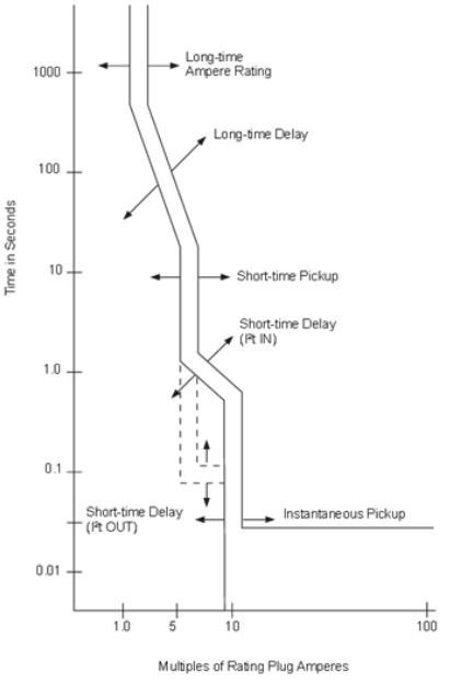
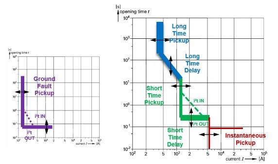
Proper primary injection testing of low voltage circuit breakers (LVCB) will confirm that they trip at the correct times and can properly isolate a fault. A coordination study is performed, and parameters are set to minimise the amount of interruption to other equipment. The characteristics of the circuit breakers are presented in the form of trip curves, and each circuit breaker will have a unique trip curve published by the manufacturer. The trip curves will have bands, or limits, that show how long it takes for the circuit breaker to trip when a certain amount of current is applied; the current is typically presented in multiples of the rated current. As long as the circuit breaker trips within the specified band, it operates correctly. You may perform up to four primary injection test types to verify that the LVCB is working correctly: a long time test, short time test, instantaneous test, and earth/ground fault test. The long, short, and ground fault tests all have a delay component. In contrast, the instantaneous test trips the circuit breaker immediately.
The long time test is a test of the overload function and requires two settings. The first setting is the pickup, which determines the load current level that is tolerable before an overload condition occurs. The second setting is the time delay that determines how long the overload condition is acceptable. Systems are generally designed to handle overload conditions for a short time. Still, damage will occur if the overload persists for too long. You typically perform a long time test at 3 times the rated current.
The short time test is also an overload test with a pickup time like the long time test but has a shorter duration with a higher current. Typical currents are at 6 times the rated current. A short time setting on the breaker is used to allow high current loads for a short duration, for example, a motor starting.
The instantaneous trip conditions test the breaker under fault conditions. Therefore, there is no intentional time delay built in, and the breaker should trip within milliseconds. If the circuit breaker fails to trip and clear the fault, this may result in damage to equipment or personnel. Additionally, an upstream breaker may need to clear the fault, resulting in other electrical system components unrelated to the fault being shut down. An instantaneous trip is typically tested using 8 to 12 times the rated current.
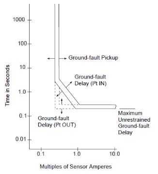
An earth/ground fault trip in the circuit breaker occurs when higher-than-normal currents flow through the ground path. Like the long time and short time functions, the ground fault has both a pickup current and a delay time. Both can be adjusted to fit the coordination study. There is typically a maximum delay that is permitted from ground fault conditions.
Each test is performed separately for each phase. As long as the trip time falls between bands on the time-current curves, the circuit breaker is considered to be in working condition.
Note: the ground fault sensor must be disabled to test long, short, and instantaneous trips.
User guides and documents
FAQ / Frequently Asked Questions
The output current of the unit is considerably affected by the strength of the source. At 480 V, the SPI can draw up to 800 amps (for a very short time during instantaneous tests). Adding 40 ft of cable will result in a 1 % voltage drop, which roughly corresponds to a similar loss in output capability.
The SPI4000 will work on a smaller breaker, such as a 100 amp one, and its output is similar to that of a DDA high current test set. You can expect similar performance as you would from a DDA on a 100 amp breaker. However, it’s important to note that the output of the SPI4000 (or any high current test set) is influenced by the voltage drop experienced during operation. A 100 amp breaker is typically fed by smaller wire compared to a 225 amp breaker. During high current tests, such as an instantaneous test, the SPI can draw over 800 amps of current, and the voltage drop will be more pronounced on a 100 amp service than it would be on a 225 amp service. Since this high current is typically of very short duration, the 100 amp breaker will not trip. However, the voltage sag may be more significant, slightly limiting the unit’s full output capability.