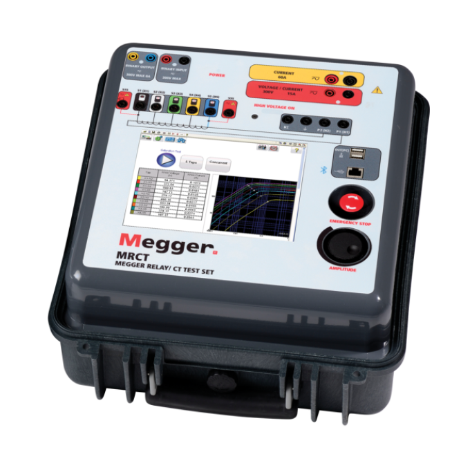
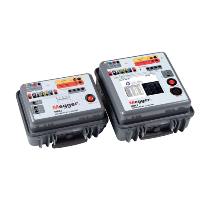
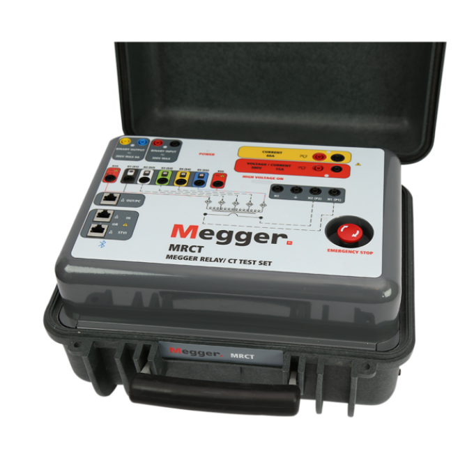
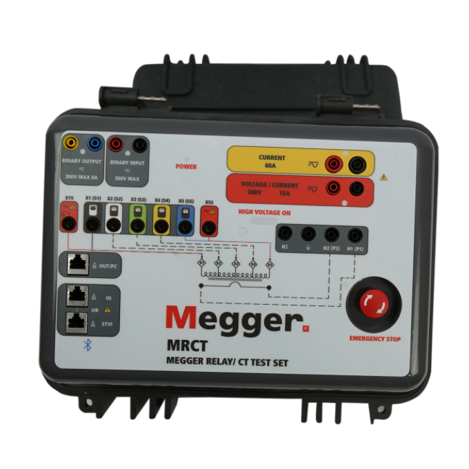
MRCT relay and current transformer test set
Reduce testing time by 20 % on multi-tap CTs
The patented system allows simultaneous measurement on all taps during current transformer testing, increasing efficiency and productivity.
Compact, portable, and lightweight
The smallest and lightest 2 kV secondary voltage injection unit on the market.
One button automated test mode
With one click, the MRCT performs winding resistance, demagnetisation, ratio, polarity, phase deviation, and insulation resistance on your CT, all without a single lead change. Results are displayed during testing and the report is created automatically when finished.
Enhanced ratio accuracy
With up to ± 0.1 % ratio accuracy, the MRCT can be used to test both metering and protection class CTs.
![](/sites/g/files/utfabz201/files/styles/megger_square/public/acquiadam/2022-11/MRCT_WEBI_001.png?itok=3YY9wqDU)
![](/sites/g/files/utfabz201/files/styles/megger_square/public/acquiadam/2022-11/MRCT_WEBI_002.png?itok=x_JY4q6b)
![](/sites/g/files/utfabz201/files/styles/megger_square/public/acquiadam/2022-11/MRCT_WEBI_003.png?itok=yMIeZpOy)
![](/sites/g/files/utfabz201/files/styles/megger_square/public/acquiadam/2022-11/MRCT_WEBI_004.png?itok=FtJK8uVR)
Über das Produkt
- Branchenführend bei Messdauer - patentierte gleichzeitige Mehrstufenmessungen verringern die Prüfzeit um 20 % bei mehrstufigen Stromwandlern
- Verbesserte Messgenauigkeit zur Unterstützung von Messklassen-Stromwandler-Prüfungen
- Kleinstes und leichtestes Einspeisegerät für 2 kV Sekundärspannung auf dem Markt
- Integriertes Einphasen-Relais-Prüfsystem
- Universalprüfen von Schaltstationen-Sekundärkreis mit 300 V & 60 A Generatoren
- Gruppenweises Prüfen: Entmagnetisierung, Kniepunkte, Verhältnisse, Sättigungskurven
- Misst mit einem Kabelanschluss alle Verhältnis- und Sättigungskurven bei mehrstufigen Stromwandlern integrierte Isolationswiderstandsprüfung
Einmal anschließen, alle Stufen prüfen
Mit dem MRCT haben Sie die Stromwandler vollständig unter Kontrolle. Sie prüfen Entmagnetisierung, Wicklungswiderstand, Wicklungsverhältnis, Sättigungskurven, Polarität, Phasenabweichungen und die Isolation.
Das MRCT berechnet automatisch Verhältnisfehler, Sättigungskurven und Kniepunkte. Zudem stellt es einen variablen und Mikroprozessor gesteuerten Spannungs- und Stromausgang sowie Präzisionsmesstechnik zum automatischen Prüfen von Einzel- und Mehrfach-Verhältnis-Stromwandlern bereit. Das reduziert die Prüfzeit und erhöht die Produktivität – auf allen Stufen mit einem Knopfdruck und ohne Wechsel der Kabel.
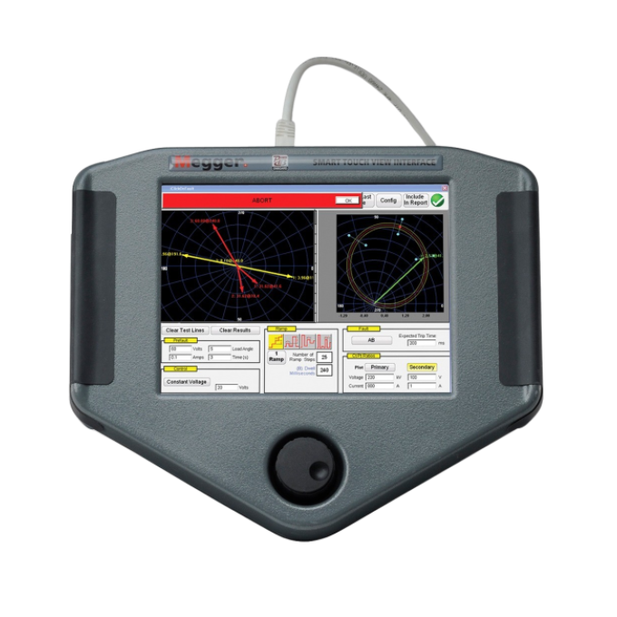
Sie steuern MRCT entweder über das Smart Touch View Interface (STVI) von Megger, über einen externen PC oder über den optional integrierten Vollfarb-LCD-Touchscreen. Auf ihm lesen Sie alle relevanten Daten während der Prüfungsdurchführung ab und betrachten gleichzeitig die Stromwandler-Sättigungskurve. Mit einem Tastendruck führen Sie mit MRCT eine Stromwandler-Sättigungsprüfung durch und berechnet den Nenn-Kniepunkt. Die Sättigungsprüfung kann bei einer Frequenz von 50 oder 60 Hz bis zu 2.000 V nach IEC durchgeführt werden.
Technische Daten
- Asset under test
- Capacitive voltage transformer
- Asset under test
- Current transformer
- Asset under test
- Voltage transformer
Verwandte Produkte
Fehlerbehebung
Power off the MRCT and shut down your PC. Make sure that you have connected the ethernet cable to the MRCT and your PC. Power both units on with the cable connected.
Ground/earth issues often cause ratio errors:
- The MRCT requires proper grounding through the power supply cord or through the chassis using the supplied grounding strap. The unit uses this ground as a reference, so for accurate testing, ensure that the MRCT is properly grounded using the supplied chassis ground strap.
- Testing large power transformers and autotransformers: The MRCT has a ground path inside the H1 (Primary 1) lead. We include this feature in the design of the MRCT for the dissipation of induced voltage typical in high voltage substations. This design allows the MRCT to test in environments other instruments cannot. However, you must take care when connecting the primary test leads on large transformers to ensure that a ground loop is not being created. When a transformer is grounded in such a way that both sides of the CT are grounded, you have a ground loop, and the MRCT cannot correctly measure any voltage. A ground loop will result in substantial ratio errors. To correct this, check all grounding on the transformer and ensure no ground loops have been created.
- Testing in high voltage yards such as 500 and 765 kV can also cause ratio errors. A sound safety practice requires grounding one side of the CT before connecting the primary test leads to it. We recommend leaving this ground in place during testing to improve ratio results. Since the H1P1 lead contains a ground path, you must be careful not to create a ground loop by grounding both sides of the CT. Therefore, external grounding should be on the same side of the CT where you connect the H1P1 lead. Additionally, the S1S/S1 (X1) connection point on the MRCT is also grounded internally, so verify that you do not have a ground loop here. Note: The MRCT has internal relays to disconnect the internal grounds when performing insulation resistance tests. When manually grounding the asset under test, you cannot perform insulation resistance tests. You will need to uncheck these on the setup screen.
- If testing CTs inside a power transformer, the windings not associated with the CT under test need to be shorted. For example, when testing a CT on the H1 to H3 primary delta winding, you would short the H3 and H2 bushings together. Separate from this, you would also short all secondary terminals (e.g., X1, X2, X3, and X0 if it is a WYE winding). Finally, you would short the tertiary terminals if the transformer has tertiary windings. See the appendix in the MRCT user guide for further information.
- To ensure the ratio error is not due to an internal fault, you can manually ground the H1 connection point to the side of the unit (safety ground).
- If the above recommendations don’t work, there is an option under the CT settings screen. Look for a button labelled “Primary Noise Filtration”. You should enable this setting only in extremely noisy environments where you cannot obtain accurate results. If used in a non-noisy environment, this can reduce the unit’s accuracy by approximately +/- 0.05 %.
- Verify that leads are connected correctly. Make sure primary leads are connected to H1, H2, and Ground, and you are not connected to HI (high current), which is to the left of the ground connection plug.
- Verify that the red S1S (source) lead and S5S (source) leads are in the right spot, as well as the X1-X5 leads
- Check for any circulating ground connections. Both S1S and H1 points are grounded internally.
- Disable “Lead Check” in the settings menu and see if the test proceeds without the lead check enabled.
Check all connections and verify they are correct. Check under the Nameplate section in the software that “Simulated Primary Leads Swap” is not checked.
Auswertung der Prüfergebnisse
The MRCT performs ratio testing by using the voltage comparison method. The voltage applied on the secondary winding is compared to the voltage induced on the primary winding.
When you provide nameplate information, the software will present percentage deviations of the measured ratios from the nameplate ratios for each tested tap combination. The allowed tolerances will depend upon the instrument transformer's application (metering or protection). Please refer to C57.13 (IEEE Standard Requirements for Instrument Transformers), or any locally applicable standard, for further details and guidelines.
Saturation tests are used to confirm that the CT, as supplied, is of the correct accuracy rating, there are no shorted turns in the CT, and that no wiring or physical short circuits have developed in the primary or secondary windings of the CT after installation. When the test is being performed, the MRCT plots the saturation curves and calculates the rated knee point in compliance with IEEE C57.13.1, IEC 60044-1, or IEC 60044-6 based on your selection.
You can then compare test results to the instrument transformer curves provided by the manufacturer.
Compare measured winding resistance values to previous results or those provided by the manufacturer. Winding resistances are not expected to change drastically over time. Any deviation (typically above 2 %) may indicate an issue related to the wiring connections from the instrument transformer to the terminal block or shorted turns in the transformer's secondary windings. It is essential to compensate test results for temperature if you plan to compare them to historical values.
It's also crucial to perform a demagnetisation after completing this test, as outlined in IEEE C37.110.
The MRCT will automatically switch test leads to perform H-L, H-G, and L-G insulation tests in compliance with IEEE C57.13.1. You should compare the measured insulation resistance values against similar devices or circuits. Carefully investigate readings lower than those known to be good. As outlined in IEEE C57.13.1, a generally accepted minimum insulation value is 1 MΩ.
The MRCT provides a burden test option that is a separate test connection from that used for your standard CT test. In this test, you must isolate the CT from the load, i.e., the circuit connected to the CT's secondary winding(s). The MRCT is connected to this circuit, and the rated secondary current is injected. The voltage drop across the injection points can be measured and then used to calculate the burden VA. This measured burden needs to be below the rated burden of the CT; otherwise, you will need a different CT for this protection circuit.
Bedienerhandbücher und Dokumente
Software und Firmware
MRCT
MRCT Firmware
latest version
FIRMWARE UPDATE
To Install MRCT FW 6.014 on an MRCT without Integrated Display
A) Using a PC
- Extract the file "MRCT_Firmware_6_014" from the downloaded zip file to your PC
- Turn on the MRCT
- Start PowerDB and connect the PC to the MRCT
- Select the System button to go to System Configuration screen
- Select Update Firmware button
- Browse to the location of the file MRCT_Firmware_6_014 on your PC
- Select this file then select OPEN
- The FW Update process will begin
- When the update is complete, the MRCT will tell you to reboot when you hear clicking
- After powering up, select the System button to go to System Configuration screen
- Select View Versions button
- Verify FW version is 6.014
B) Using an STVI
- Unzip "MRCT_Firmware_6_014.zip” onto the root of a USB drive. The USB drive should now contain Megger/Updates/MRCT_Firmware_6_014
- Connect the STVI to the MRCT and turn on the MRCT
- Insert the USB device into the STVI
- Select the System button to go to System Configuration screen
- Select Update Firmware button
- On popup screen, select MRCT Firmware
- This will start the updating process
- When the update is complete, the MRCT will tell you to reboot when you hear clicking
- After powering up, select the System button to go to System Configuration screen
- Select View Versions button
- Verify FW version is 6.014
To Install MRCT FW 6.014 on MRCT with Integrated Display
- Unzip "MRCT_Firmware_6_014.zip” onto the root of a USB drive. The USB drive should now contain Megger/Updates/MRCT_Firmware_6_014
- Turn on the MRCT
- Insert the USB drive into the MRCT
- Select the System button to go to System Configuration screen
- Select Update Firmware button
- On popup screen, select MRCT Firmware
- This will start the updating process
- When the update is complete, the MRCT will tell you to reboot when you hear clicking
- After powering up, select the System button to go to System Configuration screen
- Select View Versions button
- Verify FW version is 6.014
PowerDB Software
Onboard install files are for FREJA, RTMS, SMRT and STVI local device installation.
PC install is for remote operation of a wide range of Megger test instruments including FREJA, RTMS, SMRT, STVI and BITE5.