Nouveau
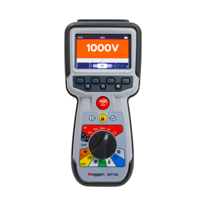
Testeur industriel multifonctions IMT100
Utilisation exceptionnellement sûre
Ses fonctions de détection rapide réduisent les risques de dommages causés à l'appareil en cas de connexion accidentelle avec des circuits sous tension ou entre phases. L'appareil comprend une fonction de détection de circuit sous tension et arrête toutes les mesures avec notification à l'utilisateur
Gamme complète pour les résistances d'isolement
L'IMT100 est fourni avec une borne de garde unique pour détecter les courants de fuite avec une résolution de 0,1 μA. Il peut effectuer des tests ponctuels, des tests temporisés et des tests de diagnostic IP (indice de polarisation) et DAR (rapport d'absorption diélectrique)
Adapté aux conditions extérieures
Sa robustesse est assurée par un boîtier surmoulé offrant un niveau de protection IP54 contre l'eau et la poussière. Il est fourni dans une mallette de transport industrielle polyvalente idéale pour transporter des accessoires et des outils de terrain supplémentaires
Alimentation par batterie pour votre tranquillité d'esprit
L'IMT100 est fourni avec six piles rechargeables NiMH et un chargeur de batterie secteur. Plus de 1 200 tests d'isolement ou 1 200 tests de continuité peuvent être effectués avec une seule charge. L'IMT100 peut également être utilisé avec six piles alcalines standard 1,5 V (AA), au lithium 1,5 V (LiFeS2) ou NiMH 1,2 V.
Jeu complet de cordons de test amovibles
Les cordons de test fournis sont livrés avec des pinces et des sondes interchangeables pour différentes applications. Le kit comprend des connecteurs pour les systèmes photovoltaïques, une sonde distante et un jeu de cordons pour résistance d'isolement, des sondes et des pinces Kelvin à faible résistance, ainsi qu'un capteur de température
![](/sites/g/files/utfabz201/files/styles/megger_square/public/acquiadam/2024-01/IMT100_PRODWEB_010.png?itok=bD2Wo8mn)
![](/sites/g/files/utfabz201/files/styles/megger_square/public/acquiadam/2024-01/IMT100_PRODWEB_003.png?itok=G8fEZLxS)
![](/sites/g/files/utfabz201/files/styles/megger_square/public/acquiadam/2024-01/IMT100_PRODWEB_11.png?itok=lfXl1bc5)
À propos du produit
Le testeur industriel multifonctions IMT100 est un instrument polyvalent offrant une gamme complète de tests de résistance d'isolement et de faible résistance. Il permet également de mesurer la continuité, l'inductance, la capacité, la tension et la température.
L'IMT100 peut mesurer une résistance d'isolement de 100 Ω à 200 GΩ avec des tensions de test de 50 V, 250 V, 500 V, 1 kV, et une tension variable sélectionnable. Il est équipé d'une borne de garde et prend en charge plusieurs fonctions de diagnostic de résistance d'isolement, notamment l'affichage d'une valeur ponctuelle, le rapport d'index de polarisation et la mesure d'isolement sur une durée définie.
L'IMT100 offre une fonction unique de test de faible résistance numérique en technologie quatre fils reposant sur une alimentation stable pouvant délivrer 200 mA sur des circuits longs avec une gamme de résistance de 1 mΩ à 10 Ω. Il propose différents modes de test sélectionnables via un clavier programmable : bidirectionnel, unidirectionnel, automatique et continu. Le sélecteur de fonction et les claviers programmables sont faciles à utiliser, avec ou sans gants, et l'écran graphique couleur de l'appareil facilite la sélection des fonctions et la prise de mesures.
L'appareil est également doté d'un thermocouple (CAT III à 600 V) qui permet de mesurer la résistance d'isolement avec une compensation de température.
La fonction LRC permet également à l'IMT100 de déterminer automatiquement si l'élément principal de la charge est inductif, capacitif ou résistif, et d'afficher le résultat à l'écran. Chaque fonction et fréquence peut également être définie sur 120 Hz ou 1 000 Hz.
L'IMT100 dispose d'une mémoire de stockage de données pouvant enregistrer jusqu'à 256 résultats de test avec des noms et des dates individuels. Les résultats peuvent ensuite être téléchargés sur une clé USB ou affichés sur l'appareil grâce à un tableau de bord de rappel des résultats de test dédié avec guide de couleurs.
L'IMT100 a été conçu pour offrir une sécurité d'utilisation exceptionnelle. Ses fonctions de détection rapide réduisent les risques de dommages causés à l'appareil en cas de connexion accidentelle avec des circuits sous tension ou entre phases.
Si des mises à jour logicielles sont publiées sur le site Web de Megger, ce qui arrive occasionnellement, l'appareil peut être mis à jour en branchant simplement une clé USB sur l'IMT100 contenant le fichier de mise à jour du micrologiciel dans le répertoire racine. L'IMT100 lance alors automatiquement le processus de mise à jour.
Autres lectures et webinaires
Produits connexes
Dépannage
Any warning conditions while using the IMT100 will appear on the display with an error code. Screen instructions will guide you through the troubleshooting process.
If the instrument does not behave as normal, and the warning messages do not disappear, this could be an indication that the instrument has a fault it needs to be repaired.
In depth details can be found in the instrument’s user guide, or via our technical support lines, however the below outlines the warning messages and their meanings:
- Test failure - Lost connection
Should the connection be lost during the test, the IMT100 will notify you. You can re-make the connection then restart the test after a few seconds by pressing the test button or by reconnecting to a test piece. Failed export
If the export fails, the IMT100 will notify you. This may be because the receiving USB device is faulty, is disconnected, full, or in some other way fails.The IMT100 will return to its previous screen.
Fuse Failure
If a fuse fails, no measurements can be carried out. A message will appear each time you try to run a test.Close the message by pressing tick/check button and refer to the user guide
NOTE: A fuse failure warning could indicate a very low insulation resistance. Check the lead connection, and try again.
- Battery Low
The battery is too low to perform a test. Please charge the batteries or replace them to continue using safely the instrument. Charging Fault
A generic charging fault warning screen.Turn the instrument off and disconnect the charger. Then reconnect and try again.
Battery not chargeable
The battery settings are not correct to allow battery charging.Check the correct battery type is in the instrument. Refer to the user guide for more information.
Check the battery settings are NiHM. Refer to the user guide for more information.
Battery Charging Warning
Only NiHM battery cells are rechargeable.
Do not attempt to recharge alkaline or lithium cells, this action is a high potential fire hazard.When charging the IMT100 while the instrument is off, an animated battery will display across the screen to show charging is taking place. Once the battery is fully charged the screen will display a solid green battery.
- Code 1000 or higher
Follow the instructions on the screen. The instructions will suggest rebooting the instrument and if the problem persists, contact Megger. The screen displays a “Voltage Detected” warning during a test.
Even if you don’t expect it, a voltage can be present or can develop during a test. The instrument will inhibit a test when the voltage detected exceeds dangerous limits and will stop the test. This voltage threshold can be set as a lockout voltage.The lockout voltage is active on all test modes. It is hard-coded to activate at 20 V. The only exception is the insulation resistance tests, where the lockout voltage can be set as 20 V, 30 V, 50 V, or 75 V.
If the instrument does not behave as normal, and the warning messages do not disappear following the screen instructions, please contact our technical support lines or an authorised Megger service centre for evaluation and repair.
Interprétation des résultats de test
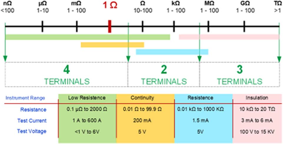
A low resistance measurement is typically a measurement below 1 Ohm. At this level, it is important to use test instruments that will minimise errors introduced by the test lead resistance and contact resistance between the probe and the material under test.
At this level, standing voltages across the item being measured, like thermal electromotive forces, known as EMF, at junctions between different metals can cause errors that, need to be identified.
A summary of the different methods used to measure resistance is shown below for a better understanding of the instrument capabilities and testing ranges.
![Low resistance testing](/sites/g/files/utfabz176/files/inline-images/IMT100-1.jpg)
Testing conditions at the time of tests can also provide essential information. Maintain records of the temperature, humidity, altitude, and any electrical interference recorded by the instrument to allow space for further corrections in the tests results.
There are different approaches towards expected values on a test. International standards suggest best practices and expected values. Notably, for photovoltaic applications, the UL 2703 suggests specific applications for racking assemblies, clamps and module fasteners, and grounding lugs, while the IEC 60512 suggests specific values on connector resistance, which is applicable for many uses, including photovoltaic and electric vehicles.
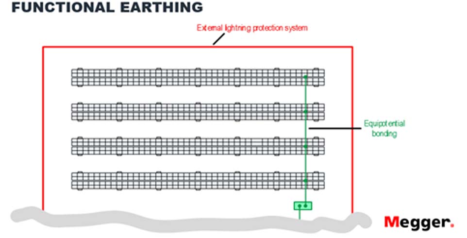
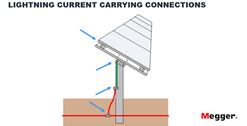
This test is vital when detecting changes in electrical bonding and mechanical equipotential structures, particularly in photovoltaic systems exposed to heavy winds, storms, snow, and corrosive environments. Below, there are some examples of where to look for these changes in equipotential bonding points:
![](/sites/g/files/utfabz176/files/inline-images/IMT100-2.jpg)
![](/sites/g/files/utfabz176/files/inline-images/IMT100-3.jpg)
![](/sites/g/files/utfabz176/files/inline-images/IMT100-4.jpg)
A good insulation resistance value means a relatively high resistance to current flow, as well as the ability to maintain a high resistance.
Insulation resistance is highly temperature dependent, and thus the results should be corrected to a standard temperature, usually 40ºC. While temperature effects will be covered later, a good rule of thumb is that for every 10 º C increase in temperature, the current doubles, and resistance halves. The key to making the test valuable is consistent timekeeping, effective record keeping, and constant trending of results.
Minimum acceptance values for insulation testing and test voltages are recommended by international standards, like the IEE and the ANSI, based on the voltage rating of the system to be tested. Some guidance is provided in the following tables:
![](/sites/g/files/utfabz176/files/inline-images/IMT100-5.jpg)
![](/sites/g/files/utfabz176/files/inline-images/IMT100-6.jpg)
The resistance and insulation resistance tests of a component can vary with its temperature. To use the instrument with the temperature compensation function enabled, a temperature measurement must be carried out to establish the temperature of the unit under test.
The thermocouple supplied with the IMT100 is set as default as type “T” and can also be configured for “J” and “K” type thermocouples.
The temperature compensation is set to “OFF” by default, and it is available in a selection of test range sub-modes:
- Insulation resistance
- IR tests
- Three phase test
- Timed test
- DLRO - Low Resistance Ohmmeter
- Uni-directional
- Bi-directional
- Three-phase
Diagnostic insulation tests electrically stimulate the insulation and measure the response. Dependent upon that response, we can draw some conclusions about the condition of the insulation.
Diagnostic insulation testing covers a very wide range of techniques, and these are:
- Spot reading test(IR)
The spot reading test is the simplest of all insulation tests and the one most associated with lower voltage insulation testers; the test voltage is applied for a short, specific period of time. Polariszation iIndex tTest (PI)
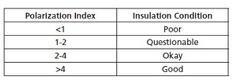
This requires only two readings followed by a simple division.IEEE standard 43-2000, Recommended Practice for Testing Insulation Resistance for Rotating Machines, defines PI as the ratio of insulation resistance at 10 minutes divided by insulation resistance at 1 minute since the thermal mass of the equipment being tested is usually so great that the overall cooling which takes place during the 10 minutes of the test is negligible.
In general, a low ratio indicates little change, hence poor insulation, while a high ratio indicates the opposite.
![](/sites/g/files/utfabz176/files/inline-images/IMT100-7.jpg)
![](/sites/g/files/utfabz176/files/inline-images/IMT100-8_0.jpg)
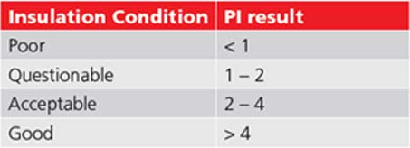
PI results > 1.5 are regarded as acceptable by IEC60085:-01:1984 for thermal class rating A, and PI results > 2.0 for thermal class ratings B, F, and H.
Dielectric Absorption Ratio(DAR)
Measures resistance over time expressed as a ratio of resistance at time t2 divided by resistance at time t1.
The assumption is that insulation temperature does not vary widely over the duration of the test so the resulting DAR and/or PI value are temperature independent.
This test is defined as the ratio of insulation resistance at 1 minute divided by insulation resistance at 30 seconds.
In general, a low ratio indicates little change, hence poor insulation, while a high ratio indicates the opposite.
Timed insulation resistance test T(s)
A timed test will automatically terminate an insulation test after a preset time. The default timer is set to 1 minute and is adjustable within the settings function. This is a useful feature that saves you from watching the display for the full duration of the test, and the possibility of missing the 1-minute reading.